


How do I wire the trigger/input signals with a
common neutral?
A short guide on how to wire the tigger/input signals for your Nexus unit with a common neutral connector


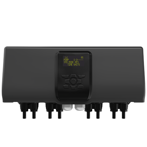
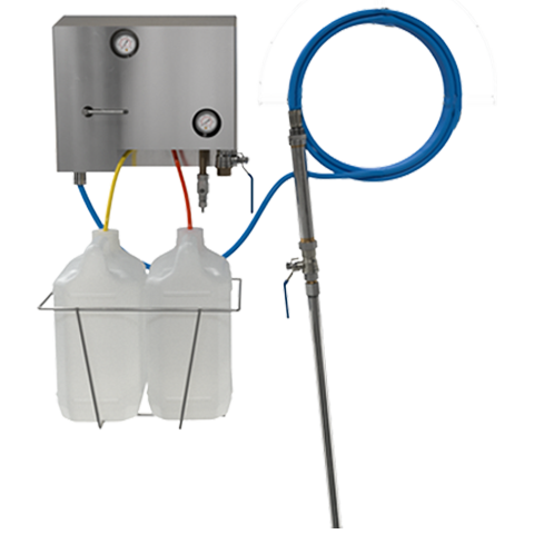
Step 1
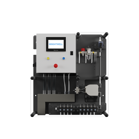
The Trigger Signals are prewired into your Nexus Unit A rail as shown.
Step 2
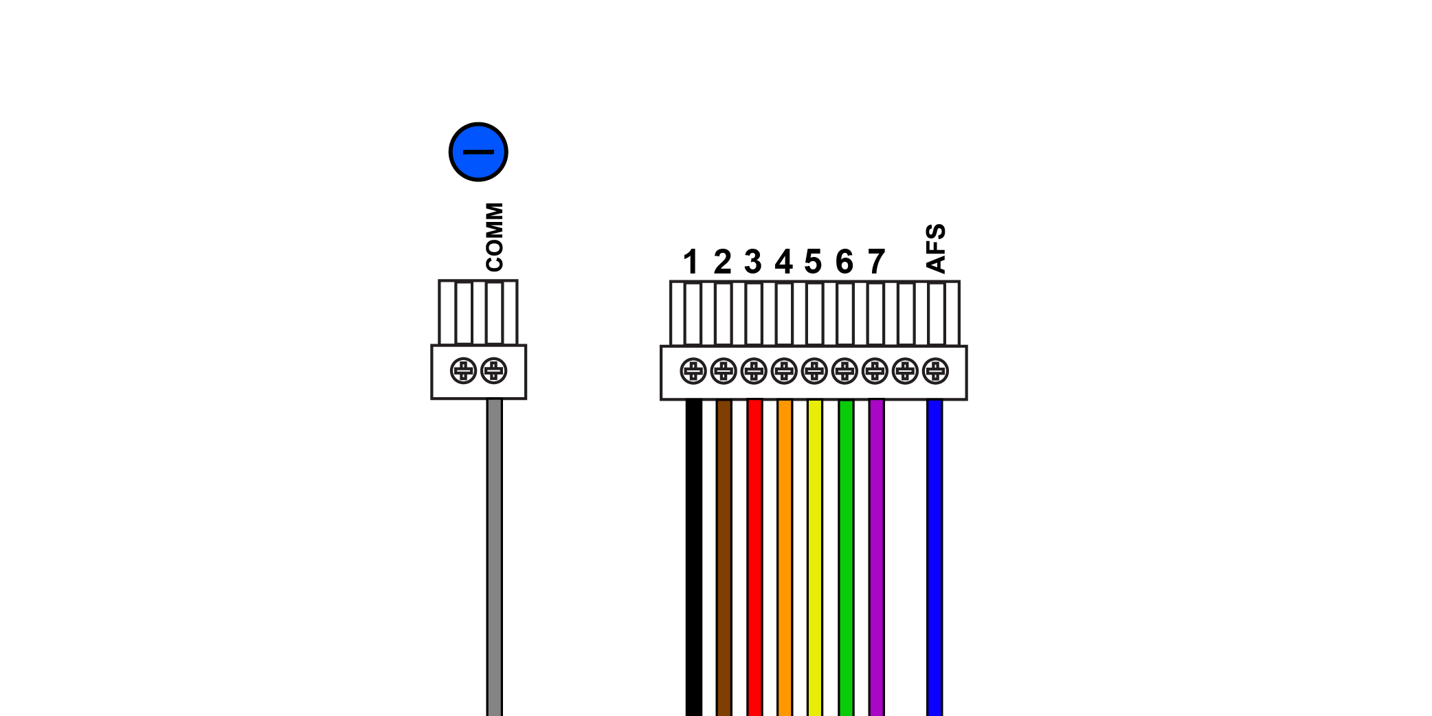
The wiring guide is as follows:
COMM – Grey – Common Neutral
1 – Black – Input/Trigger 1
2 – Brown – Input/Trigger 2
3 – Red – Input/Trigger 3
4 – Orange – Input/Trigger 4
5 – Yellow – Input/Trigger 5
6 – Green – Input/Trigger 6
7 – Purple – Input/Trigger 7
AFS – Blue – Auto Formula Select
Step 3

Wire these into the Washing machine connections and your unit is ready to use.
Step 4
Connect any common trigger signals into the A rail as shown.
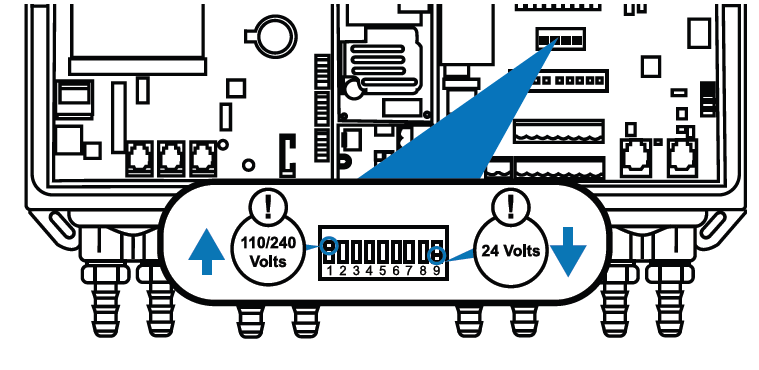
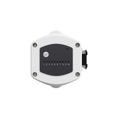
Step 5
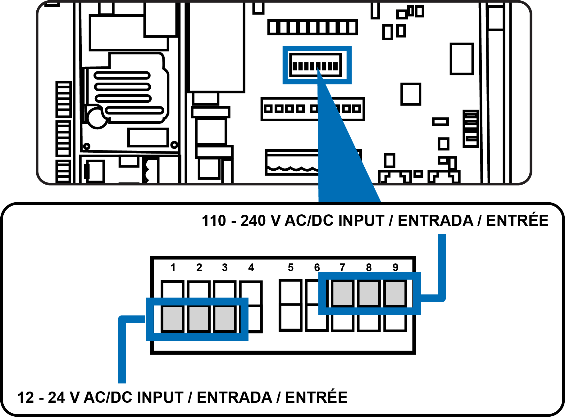
The final step is to set the Trigger Signal Dip Switch. This depends on if the inbound signal is a HIGH or LOW voltage input. Please put the switch to the top for HIGH voltage or the bottom for LOW voltage.
Step 6
The last step is to define if the trigger signals are HIGH or LOW. High are for voltages between 110-240 volts. Low is for voltages between 12-24 volts.
Keywords
– Wiring the trigger
– Wiring the input
– Trigger
– Signal
– Common